PBR Theory
Defining PBR
PBR stands for Physically Based Rendering. It’s a concept/methodology for representing realistic shading/rendering of surfaces, representative of real world materials. It is not however a strict set of rules but rather a guideline to achieve physically based accurate materials.
1. Light Rays
- Light can exhibit properties of both a wave and a particle.
- The Ray model of light describes the interaction of light and matter.
- A ray of light travels in a straight line when passing through a homogeneous transparent medium such as air.
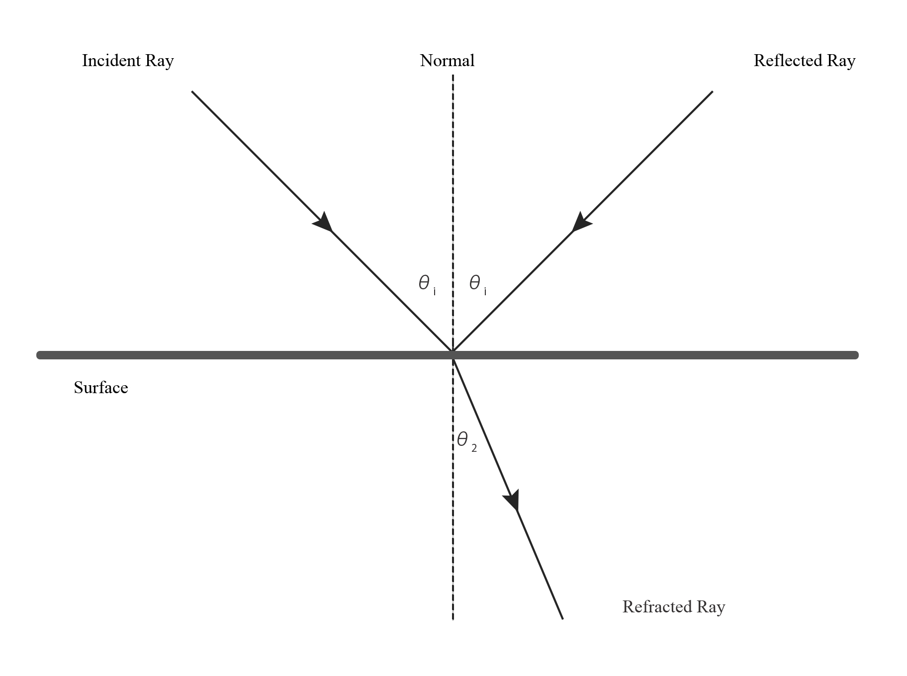
- Incident Ray is the ray that hits the surface
- Reflected Ray is the ray that is reflected of a surface.
- The angle at which a ray hits the surface is the angle of incidence.
- The angle at which a ray reflects off a surface is the angle of reflection.
When a light ray hits a surface, The ray splits into two possible directions, resulting in either of the following event:
- Reflected Light
- It reflects off a surface and travels in a different direction. This follows the Law of Reflection, which states that the angle of reflection is equal to the angle of incidence.
- Refracted Light
- It passes from one medium to another in a straight line.
The Law of Reflection states that the angle of reflection is equal to the angle of incidence.
At the surface, the ray is either reflected of refracted and it can be eventually absorbed by either medium. Absorption however does not occur at the surface of the material.
2. Absorption & Scattering (Transparent & Translucency)
Light rays that travel through a translucent material such as skin or a single blade of grass can be absorbed or scattered.
When light is absorbed:
- The light intensity decreases as energy is transformed/transferred into another form, usually heat.
- It’s colour changes as the amount of light absorbed depends on the wavelength but the direction of the light ray remains unchanged.
When light is scattered:
- Ray direction changes randomly and the amount of deviation to the direction depends on the material.
- Scattering randomizes light direction but does not change the intensity.
Light rays can either be absorbed or scattered when travelling through a translucent material.
If there is no scattering and the absorption is low, rays can pass directly through the surface. An example of this is glass or water:
- In a clear pool of water, you can see a great distance if you open your eyes.
- If the pool is dirty, the dirt particles will scatter the light, lowering the clarity.
The further light travels in such a medium, the more it is absorbed and/or scattered. Therefore something like a thickness map can help dictate how much light is absorbed or scattered.
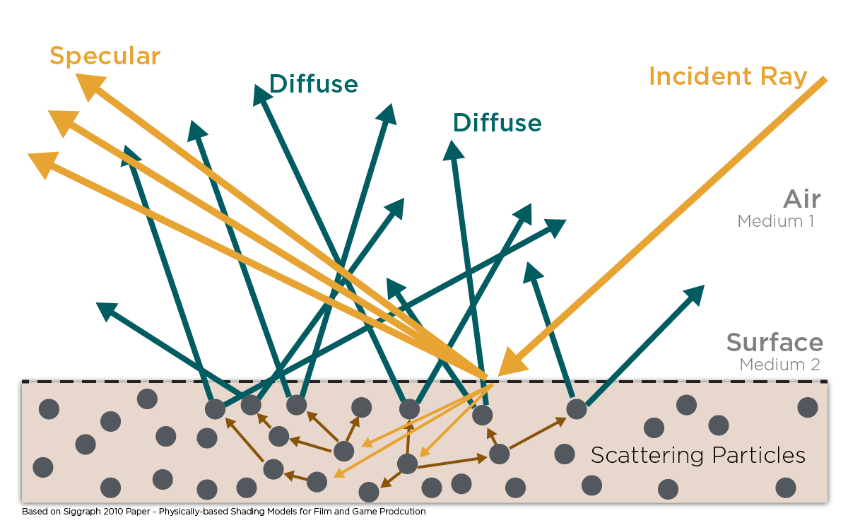
3. Diffuse & Specular Reflection
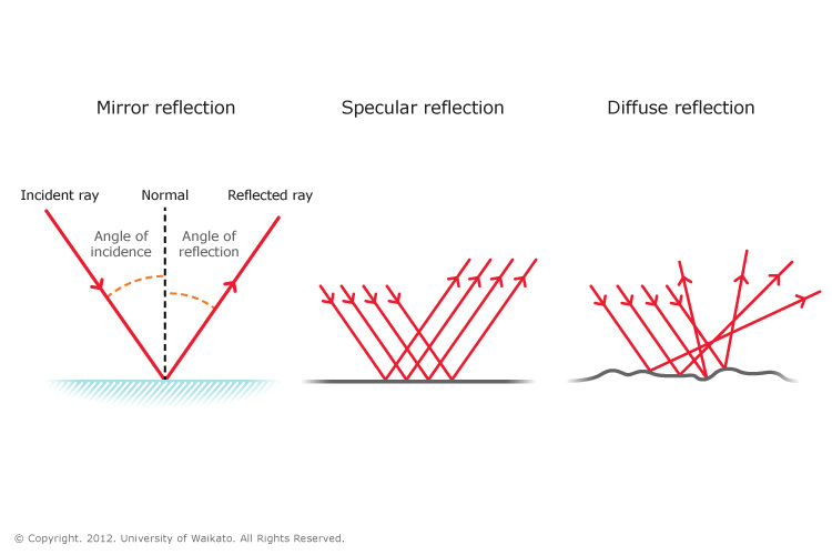
- Specular Reflection
- Refers to light that is reflected at the surface. Light is reflected off the surface and travels in a different direction.
- Specular reflection
- Follows the Law of Reflection which states that on any perfectly planar surface, the angle of reflection is equal to the angle of incidence.
- Most surfaces are irregular and the angle of reflection will vary randomly based on the surface roughness. This is known as diffused reflection.
- Whether it’s specular or diffuse reflection, though the light direction changes, the intensity of the light remains constant.
The total amount of light reflected is the same in both specular & diffused reflections.
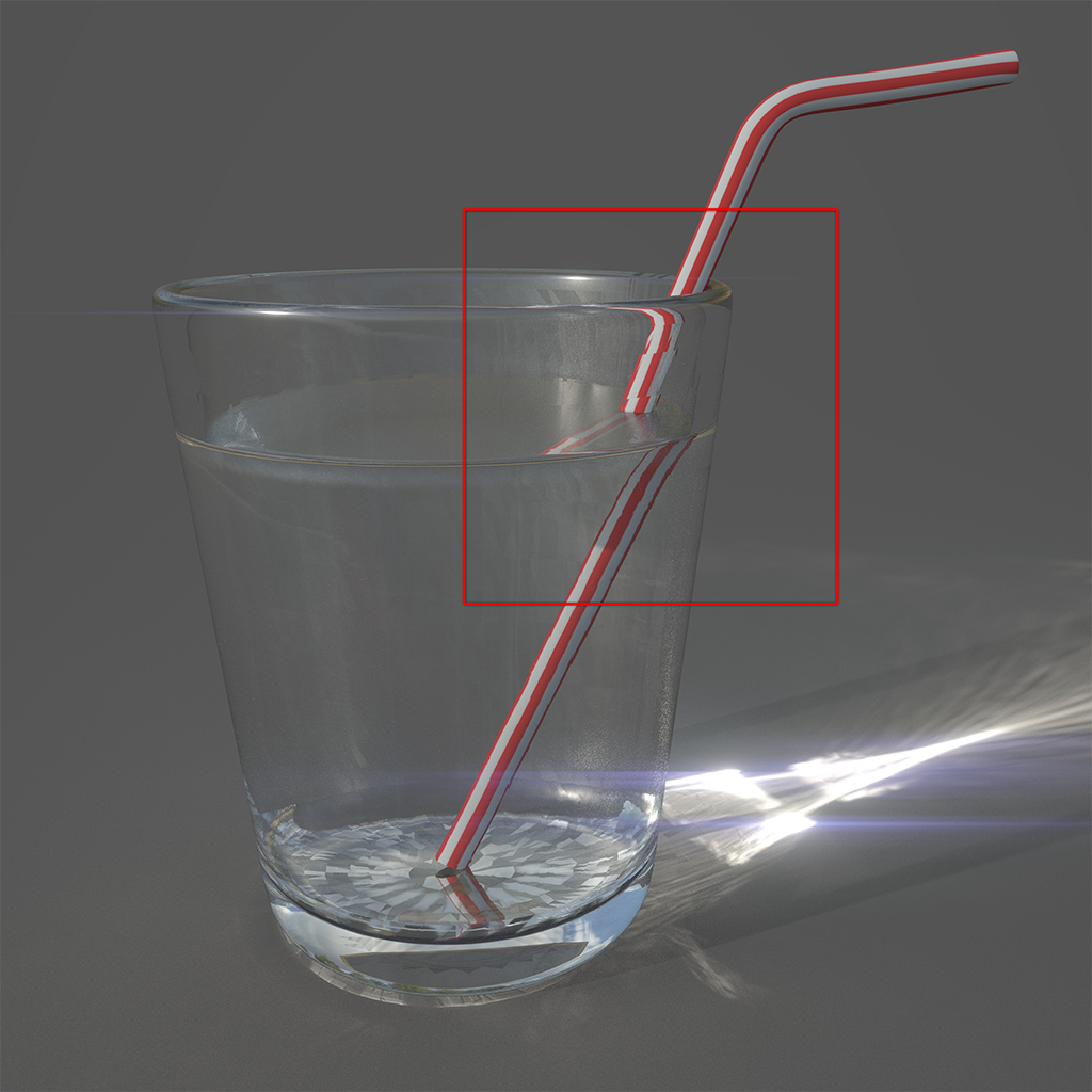
Refraction is a change in a light direction. When light moves from one medium to another, it changes speed and direction. This is most evident in transparent materials such as glass and water.
- Diffuse reflection
- Diffuse reflection is light that has been refracted. A light ray passes from one medium to another. Light is then scattered multiple times within this objects and eventually refracts out of the object at roughly the same angle as when it entered the second medium. The index of refraction or IOR is an optical measurement that measures this changes in direction. IOR determines how much the ray will bend when it passes through another medium.
Diffuse materials are absorbent. If the refracted light travels for too long in a diffuse material, it may be absorbed completely. If the light does exit this material, it has likely travelled only a very small distance from the point of entry.
In a traditional shading sense, there two common models of representing reflectivity in diffuse reflections:
- Lambertian
- Oren-Nayar
With specular reflections, there are are 4 common models for describing the perceived brightness of a surface material:
- Phong
- Blinn-Phong (Usually just referred to as Blinn to avoid confusion)
- Cook-Torrance (Microfacet)
- Anisotropic
- Translucent Materials
- Materials that have high scattering & low absorption. Examples of translucent materials include:
- Smoke
- Fog
- Milk
- Skin
- Jade
- Marble
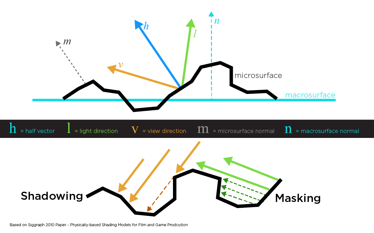
Microfacet Theory
Both diffuse & specular reflection are dependant on the surface irregularities where the light rays intersect with a medium.
The effect of roughness on diffuse reflections is less visible because of the scattering that occurs inside the material. Because of this the outgoing direction of the ray is independent of surface roughness and incident direction. The Lambertian model for diffuse reflection completely neglects roughness.
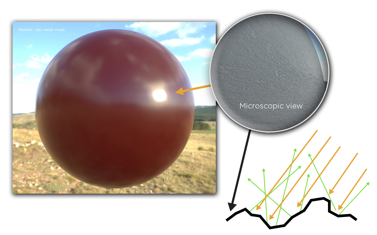
Surface irregularities can also be described as surface roughness. Other common or similar names include roughness, smoothness, glossiness or micro-surface. The name are heavily dependent on which PRB workflow is in use. Whether it be Metallic/Roughness or Specular/Gloss. Either way these terms are all used to describe the same thing which is sub-texel geometry detail.
Surface irregularities are authored in the roughness/gloss map. A physically based BRDF is then apply based on the microfacet theory. Microfacets can be described as small-scaled planar details on a surface with varying degrees of orientation and shape. Each of these small planes reflect light in single direction based on it’s surface normal.
 「The Comprehensive PBR Guide by Allegorithmic - vol. 1 Light and Matter : The theory of Physically-Based Rendering and Shading」©Allegorithmic
Microfacets whose surface normal (m) is oriented exactly halfway between light direction (l) and view direction (v) will reflect visible light. In cases however where the half normal (h) is equal to the microsurface normal, not all microfacets will contribute as some will be blocked by shadowing caused light direction (l) by or masking due to view direction (v).
Surface roughness at a microscopic level cause light diffusion. This is how blurred reflections can occur because the light rays have been scattered by the surface irregularities.
4. Colour
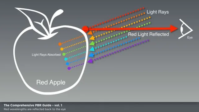
Colour is the visible response due to wavelengths of light reflected from a surface. When light hits a surface, these wavelengths are either absorbed by the object and reflected both specularly and diffusely. The wavelength of light that is reflected back is what we perceive as colour.
As an example, take the skin of a red apple. We perceive an apple to be red because all other wavelengths have been absorbed while the red wavelength is reflected.
An apple will also have specular highlights that consists of the same colour as the light source because for dialectric materials, or materials that do not conduct electricity, specular reflection is independent of wavelength.
For dialectric materials, specular reflection is never coloured, that is to say, it is never the same colour and the reflected wavelength of that object.
5. BRDF
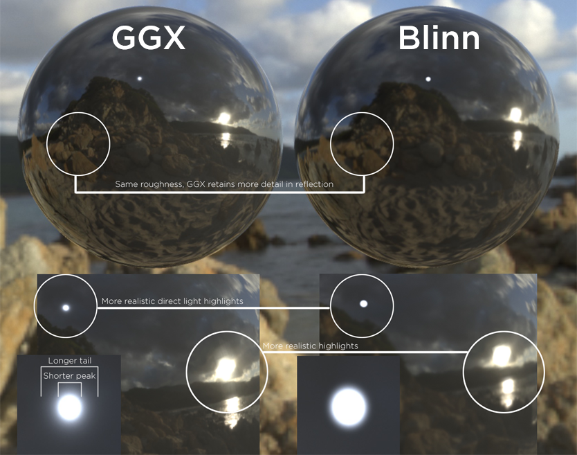
A bidirectional reflectance distribution function (BRDF) is a function that describes the reflectance properties of a surface. There are many different models of BRDF’s, some of which are not physically plausible in the real world. Some common models include:
- Disney’s BRDF (Based on the GGX BRDF)
- GGX
- Cook-Torrance
- Oren-Nayar
- Lambertian
- Blinn-Phong
- Phong (Not to be confused with Blinn-Phong)
- Ward
For a BRDF to be physically plausible, it must obey the laws of energy conservation and exhibit reciprocity. Reciprocity refer to the Helmholtz Reciprocity Principle, which states that the incoming and outgoing light rays can be considered reversals of each other without affecting the outcome of the BRDF.
In recent times, real-time engines as well as Substance and Marmoset have included or primarily utilize the GGX distribution as it represents a more accurate representation of specular distribution. This can be characterized by the shorter peak and longer tail falloff.
6. Energy Conservation
The principle of energy conservation states that the total amound of light reflected will never be more intense than when it first hits a surface. The total amount of light re-emitted by a surface, both reflected and scattered back, is less than the total amount of incoming light.
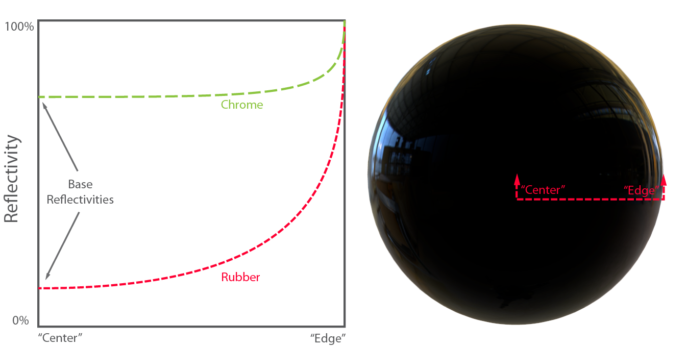
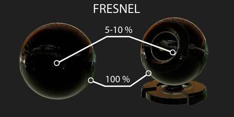
7. Fresnel Effect
Fresnel is an effect, first observed by French physicists Augustin-Jean Fresnel. The Fresnel effect states that the amount of light reflected from a surface depends on the viewing angle at which it is perceived.
Think of a pool of water. When looking straight down into a pool, perpendicular to the water surface, you will normally be able to see clearly all the way to the bottom of the pool. When viewing the water surface at this angle, you are viewing it at zero degrees to the surface normal or normal incidence.
Take another look at the pool again but this time from a glancing angle, slightly more parallel to the surface, and you will most likely notice some of its surroundings being reflected back at you. What you are seeing here is the specular reflection was mentioned earlier. In some situations, you might not be able to see below the surface at all.
 「Basic Theory of Physically-Based Rendering」©marmoset
Another example is a screen on a laptop, tablet or mobile phone that does not have a layer of anti-glare applied to it. Looking at the screen straight on, you will likely be able to view what is on the screen. Tilt the surface normal slightly away from your eye to a different direction and you will often find yourself looking at a reflection of other objects in the vicinity.
Fresnel is generally not something that we can control in a typical PBR workflow. However, in some exceptions such as UE4, there are custom Fresnel nodes that have been exposed by the engine to allow for certain unique material effects.
When viewing a surface at a grading incidence, all smoothed surface will become reflectors at near 100% at a 90-degree angle of incidence.
All surfaces are shiny to some extent and all surfaces exhibits some degree of fresnel.
For rough surfaces, the reflectance becomes increasingly specular but will not approach 100% specular reflection because of micro-facet diffusion. The angle between the normal of each microfacet and the light will differ slightly. Because light rays are more dispersed, reflections appear dimmer and softer.
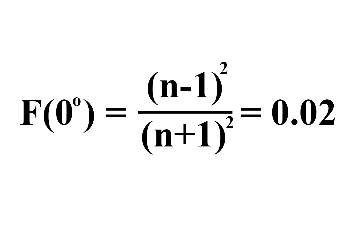
F0(Fresnel Reflectance at 0 Degrees)
When Light hits a surface straight on or perpendicular to a surface normal, a percentage of that light is reflected as specular. The amount of reflected light can be derived from a surface’s IOR. F0 refers to the fresnel reflectance at 0 degrees to the surface normal, usually described in either percentages or decimal linear values.
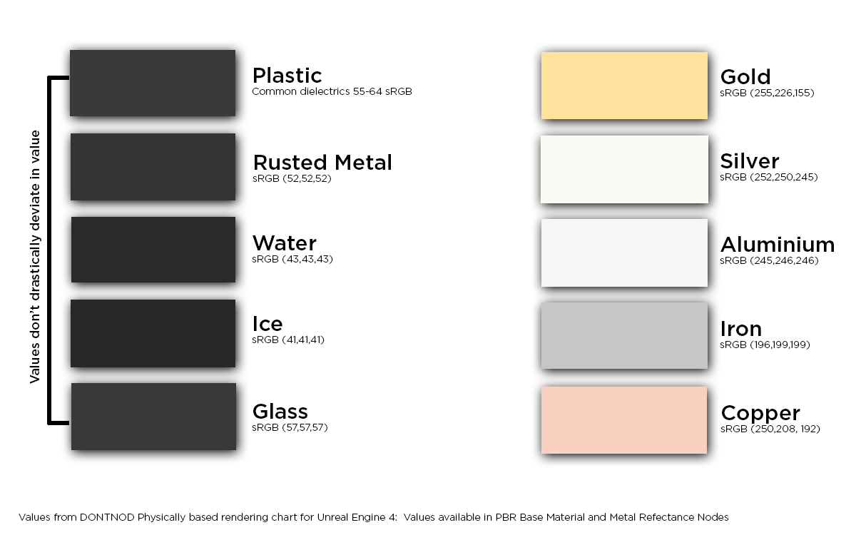
General F0 Ranges
Dielectrics/Non-conductive surfaces: 0.02 - 0.05 or 2% - 5%
Conductors/Metals: 0.5 - 1.0 or 50% - 100%
The formula below represents how the reflectivity of a surface is thereby determined by the refractive index of a given surface.
It is the F0 reflectance value that we care about. Non-metals will return a grayscale value while metals will have an rgb value.
Non-metals/dialectrics/insulators will return a greyscale reflectance value.
Metals/conductors will return an RGB reflectance value.
The change in reflectance between between dielectrics are fairly miniscule or barely noticeable but a change exists regardless as in this diagram. The few odd materials that break this rule are certain types of gemstones which tend to have higher reflectance values.
8. Conductors & Insulators
When creating materials in PBR, it is helpful to think in terms of metals & non-metals. This will help you determine which set of guidelines to follow when authoring said materials.
This approach may not work if designing unique categories of materials such as metalloids, which comprises of both metal & dialectric properties. However, those are edge cases and 9 times out of 10, you most likely will be creating either standard metals/dialectrics.
Colour tint of metals come from reflected light. DO NOT give metals a diffuse colour.
Metals
- Metals are good at conducting heat and electricity.
- The electric field in conducting metals is zero.
- When a lightwave made of electric and magnetic field hits a metal surface, the wave is partially reflected and all refracted light is absorbed.
- The reflectance value for polished metal is around 70%-100%.
- Some metals absorbs light at different wavelengths. e.g(Gold).
- Gold absorbs blue light at the high frequency end of the visible spectrum, hence leaving just the warmth.
- Since refracted light is absorbed, the colour tint of metals come from reflected light. Because of this, we don’t give metals a diffuse colour.
- With metals, the reflectance value will be RGB and can be tinted using real-world measured values.
Metals corrode and the corroded areas are treated as dielectrics.
- Metals corrode. Metals are often exposed to different weathering elements which affects their reflective state.
- When metals corrode, their corroded parts are treated as dielectric, often denoted by black values inside a metalness map.
- In a metalness/roughness workflow, the black areas of a metallic map denotes areas that are non-metals and vice versa.
- Painted metal is also treated as dielectric. This is because paints, which act as a layer on top of the raw metals, do not conduct electricity.
- It’s a similar case with dirt, dust and any matter/materials that obscured raw metals.
Painted metals are treated as dialectrics.
- When authoring materials, it is good to also ask what state a metal material is in. Typically most metals, unless recently milled at a factory, will exhibit some for of weathering/damage/wear.
- Depending on how much weathering, there will always be some level of blending between metals and non-metals.
Dialectrics
Dialectric are materials that do not conduct electricity. Examples include porcelain, cloth & plastic. Refracted is scattered and/or absorbed and often reflect smaller amounts of light and will have al albedo colour.
Common dialectric will have a reflectance value of around 2-5% based on an F0. These values are contained within a linear range of 0.017 - 0.067 or 40-75 sRGB.
With the exception of gemstones and metalloids, most dialectrics will not have an F0 reflectance value greater than 4%.
9. Linear Space Rendering
Linear space rendering is an extremely complex topic. Some sites that go into linear space rendering:
Gamma and Linear Space - What they are & how they differ
Linear Rendering - Linear Or Gamma Workflow
Linear Lighting
Linear, gamma and sRGB color spaces
- In it’s most basic terms, linear space rendering is a workflow that provides an accurate mathematical structure for rendering a 3d scene or image.
- It creates an environment where light interaction can be represented in a credible real-world manner.
- We can’t discuss linear space rendering without discussing gamma correction.
- When encoding images for display/storage purposes, gamma correction is the optimization process of reducing bandwidth and bit allocation.
- Gamma correction leverages the human eye’s perception of brightness, which follows the cube root of luminance. This is why we still have brightness and gamma sliders in games.
- The human visual system is more sensitive to differences in darker tones than bright tones.
- Gamma correction is used to reduce calculation of bits in regions where the human visual system is unable to distinguish between tones.
- In typical image creation process, images are encoded using as encoding gamma functions like below for display devices:
- sRGB OETF (Opto-Electronic Transfer Function)
- sRGB EOTF (Electro-Optical Transfer Function)
- Gamma 2.2
- The display circuitry decodes the image using its own decoding gamma function. Typically computer monitors will have a gamma setting of 2.2. That is why when working in a linear rendering, you will often hear the term gamma 2.2 or 2.2.
- Gamma correction applied when a colour space other than linear colour space is being utilized.
- Linear colour space has no gamma correction. Working in a linear colour space is equivalent to having a gamma of 1.0, which already has correct linear computation.
- Despite working in a linear colour space however, the rendered image has to be encoded in gamma space to present accurate image rendering to the viewer.
- Computations of color values and operations on colors are perfomred in linear space.
- When computing color values, gamma-encoded values are decoded into linear values from the supplied color maps, and from colors chosen while viewing on a monitor via a color picker.
- When colour managing, this would typically involve tagging a texture map to be intepreted as either linear or encoded with sRBG or gamma 1/2.2. Computations are then carried out in linear space and the final rendered result is gamma encoded with sRGB OETF or gamma 1/2.2.
- These are the maps that you would typically flag as gamma-encoded or sRGB:
- Base Colour/Albedo
- Diffuse
- Specular
- Emissive
- These are the maps to be flagged as linear :
- Roughness
- Ambient Occlusion
- Normal
- Metallic
- Height
- Substance handles the conversion between linear and gamma space automatically on shader inputs as well as gamma correction on the computed results in the viewport.
- When using Substance materials via various integration plugins, outputs are flagged for linear/gamma space automatically throughthe plugin and hosts application’s colour management system.
The following extensions are usually gamma encoded:
- *.png
- *.jpg
- *.tga
- *.tiff
The following are usually linear:
- sRGB OETF
- *.exr
- *.hdr
10. Key Characteristics of PBR
In summary, these are some of the main characteristics of PBR:
- Everything is shiny.
- Everything has Fresnel. The BRDF is handled by the shader.
- F0 reflectance values fall within 2-5% for dialectrics and 70-100% for metals.
- Weather effects exposes the raw metals underneath. Dust, rust & dirt are treated as dialectrics.
- Energy conservation. A reflected ray is never brighter than the incoming value.
- Metals have no diffuse colour. The reflectance value may have tint.
- Specularity intensity is controlled via BRDF, roughness or gloss and the F0 reflectance value.
- Lighting calculations are computed in linear space.
- Base colour, diffuse, specular & emissive maps are usually gamma-encoded and thus should be tagged when necessary.
- Roughness, gloss, metallic, height, AO & displacement should be tagged as linear.